VCA-Hold-Function for a Moog Prodigy
Description and instructions
Attention: the below text and associated diagram makes reference to the electronic circuit and layout as given by MOOG MUSIC INC. in their 1980 Technical Service Manual for the MOOG PRODIGY Domestic Model 336A and Export Model 336BX (above serial no. 4160). However, other versions of the Prodigy circuitry are so similar that an adaptation to them is easily possibly.
1. Reasons to do the mod
This modification of the Moog Prodigy is helpful in particular when playing live.
One of the issues I had with many of the old analog synths including the original Prodigy was that the VCA-envelope was always active so that when I needed a drone tone I had to keep my finger on the respective key. The work-around to set the decay of the VCA to as long as possible was not so attractive because it meant changing the setting.
The present mod solves the above issue by simply setting the VCA to "through" at the flick of an (additional) switch. It involves installing an on-on switch and a resistor, and requires opening up one lead on the printed circuit board of the prodigy (or un-solder a resistor at one point). The mod is otherwise extremely simple.
I modified my Prodigy accordingly in 1981 and found it to add a lot in particular in terms of its live-use. I have sold the Prodigy a long time ago and unfortunately have no photos of the mod - but I did retain the schematics which form the basis for these instructions.
2. Basic functioning of the mod
The mod (shown in the circuit diagram) works on the basis of switchably feeding a (large) DC-voltage to the control input of the VCA rather than the envelope so that the VCA stays open as long as the switch is engaged.
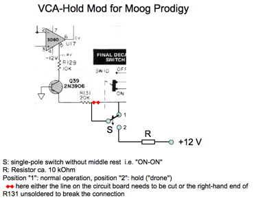
The line on the printed circuit board feeding the control input of the VCA is cut - alternatively the resistor in series to the VCA input is unsoldered on one side. A newly installed switch re-connects the circuit as before in one position and in the other feeds the DC-voltage (derived from the +12 V supply voltage via a resistor of e.g. 10 kOhms) to the VCO control input so that the VCA remains open - thus giving a "drone" or "hold" effect without the need to press a key - the pitch will remain where it was after the last key-activation. The VCA-envelope does not require adjustment for this.
3. Parts needed
To do this mod, you will need a 2-position "on-on" single-pole switch, a 10 kOhm resistor (other values from 1 to 50 kOhm will probably do fine, too), and some generic isolated wire. Of course, you need a soldering iron and solder, and something to drill a hole into your precious Prodigy ........
4. Knowledge requirements and preparations
Installing this mod is very easy for anybody having some basic knowledge about analog electronics and a bit of basic experience in mechanical workmanship and soldering of circuits.
Before doing the mod, you should familiarize yourself a bit with the circuitry of the Prodigy by downloading the schematics and service manuals from the internet. They are offered by various sites, I found them - for example - at the following addresses:
http://www.hylander.us/images/schematics/moog/MoogProdigyServiceManual.pdf
http://www.physicsenterprises.andrews.edu/diy_archive/manuals/moog/index.html#prod
http://www.pmerecords.com/Docs/ProdigyPCBLayoutsAll.jpg
http://www.pmerecords.com/Docs/Prodigy_SchematicBelow4160.jpg
http://www.pmerecords.com/Docs/Prodigy_SchematicAbove4160.jpg
http://www.pmerecords.com/Docs/ProdigyAlignmentBelow4160A.jpg
http://www.pmerecords.com/Docs/ProdigyAlignmentAbove4160.jpg
I recommend having an thorough snooping around in the insides of your Prodigy before starting modifying it. Use the circuit diagram and circuitry description together with the picture of the printed-circuit-board layout to locate the position of important circuit parts - for the present mod this will be in particular resistor R131 which right below the "Contour Amount" control on the PC board.
5. Installation
Installation is done according to the schematics shown in the figure. The schematics can be seen as two parts (which in fact also differ cosmetically in the figure): one part more to the top is a copy&paste-job from the original Prodigy schematics and shows the VCA control input circuitry with the associated components. The other (lower) part is the actual modification.
First, the line on the printed circuit board leading to the resistor R131 needs to be cut, or alternatively, the end of R131 closer to the "Contour Amount" control could be unsoldered from the board - this will break the connection nicely and has the advantage that one does not have to scrape around on the board!
The switch should next (carefully) be mounted. Choose a location you find convenient and cosmetically pleasing. You may need to de-install the circuitboard. On my Prodigy, I had positioned the switch right of the keyboard on the little black "platform".
The middle contact of the switch is now simply connected to that end of R131 which is closer to the "Contour Amount" control - this will be the end of the resistor which you unsoldered from the circuit board if you did that.
One of the other two switch-contacts is connected to the "other" contact created by opening up the line on the circuit board - either the line you cut or the contact on the board to which the unsoldered end of R131 was originally connected.
The remaining switch contact is connected (via a resistor of ca. 10 kOhms) to any +12 V supply voltage terminal you can find. An easily accessible one is the terminal of the "Filter Cutoff Frequency" control connected to R148.
That's it! Done! Put your Prodigy back together and go e.g. into a deep-bass drone-mode while have both hands free to play pads and leads on other keyboards!
6. Mod the Mod
Of course, this modification can be modified! For example, instead of connecting R131 to the +12V supply voltage, you could also connect it to a variable voltage (for example by rigging a 50 kOhm pot between the supply voltage and the switch. That way your drone-tone could be preset in level because the VCA would be kept in a controlled partial-open state.
7. Note:
Although I have installed this mod successfully in my Prodigy back in 1981 and have used it for a number of years (until I sold the synth) to very good effect, and although I cannot see any risks of the mod to the synth, I also cannot take any liability with respect to any problems or damage you might incur when doing the mod. You do this entirely at your own risk.
This description and installation instruction is written in good faith with the sole intent to provide a service to the interested public. There is no commercial intent whatsoever. Hope you like it!
8. Credits:
Thanks to my friend Matthias Schorer for enduring support and the use of his website to post this mod!
Thanks to Bob Moog for creating lots of great hardware and promoting it so well!
Download this text as PDF
Download Schematics as PDF