LFO Frequency Range Switching in a Moog Prodigy
Description and instructions
Attention: the below text and associated diagram makes reference to the electronic circuit and layout as given by MOOG MUSIC INC. in their 1980 Technical Service Manual for the MOOG PRODIGY Domestic Model 336A and Export Model 336BX (above serial no. 4160). However, other versions of the Prodigy circuitry are so similar that an adaptation to them is easily possibly.
1. Reasons to do the mod
This modification of the Moog Prodigy is helpful to get more flexibility when going for more experimental sounds.
One of the issues I had with the original Prodigy design was that the frequency range of the LFO was only suited to the more "normal" sounds involving vibrato for lead playing or filter-sweeps. Really interesting audio-range FM or very slow sweeps were not possible. This is due to the frequency range of the LFO which encompasses 0,3 - 30 Hz.
The present mod significantly expands the LFO frequency range. It involves installing a 3-position single-pole switch and 2 capacitors, and requires replacing a capacitor on the Prodigy circuit board. The mod is very simple but makes still for a rather precise adjustment of the LFO frequency due to the range switching so that the relative range of the LFO frequency pot remains the same. It is very suitable for experimenting with sounds.
I modified my Prodigy accordingly in 1981 and found it to add a lot in particular in terms of more unusual sounds - e.g. very slow filter sweeps in drones and weird FM for gong-type sounds. I have sold the Prodigy a long time ago and unfortunately have no photos of the mod - but I did retain the schematics which form the basis for these instructions.
2. Basic functioning of the mod
The mod (shown in the circuit diagram) works on the basis changing the capacitance C21 which governs - together with the resistors R106 and R107 - the LFO frequency. This is done by replacing the original capacitor C21 with a smaller one so that the basic LFO frequency is much higher - corresponding to the operation with the switch in the middle position when only C21 is active. The two capacitors C21a and C21b are connected via the switch in parallel to C21 - being much larger they drastically increase the effective overall capacitance and correspondingly decrease the LFO frequency.
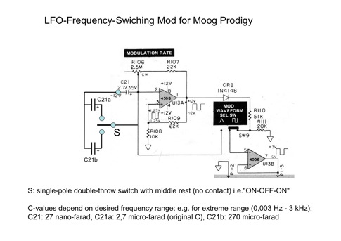
How much the LFO frequency is changed is up to you - select the capacitors accordingly using the original capacitor with 2,7 microfarad as reference. Changing the capacity by a factor of 10 will change the LFO frequency also by a factor of 10, albeit in the "other" direction: an increase of the capacity will yield a decrease in LFO frequency. In the diagram, possible values for an extreme frequency range are mentioned: decrease and increase of a factor of 100 for the two "active" switch positions. Because LFO-frequency pot itself will allow for a range of 100 (0.3 Hz - 30 Hz with the original C21-value), using a 27 nanofarad and a 270 microfarad capacitor, respectively, for the highest and lowest ranges should give you a extremely wide overall range of between 0,003 Hz and 3 kHz. I found the very low frequency not to actually usable and therefore opted for a 27 microfarad capacitor instead of the 270 microfarad one - still giving a sweep as slow as half a minute for one period. In this case, the frequency ranges in the medium- and the low-frequency positions of the switch overlap considerably but I found that convenient.
3. Parts needed
To do this mod, you will need a 3-position double-throw single-pole switch, 2 capacitors (e.g. a 27 nanofarad bipolar capacitor and a 27 electrolytic microfarad - if you cannot find these exact values use the more common 22 nanofarad and 22 microfarad values which will also do fine), and some generic isolated wire. Of course, you need a soldering iron and solder, and something to drill a hole into your precious Prodigy ........
4. Knowledge requirements and preparations
Installing this mod is very easy for anybody having some basic knowledge about analog electronics and a bit of basic experience in mechanical workmanship and soldering of circuits.
Before doing the mod, you should familiarize yourself a bit with the circuitry of the Prodigy by downloading the schematics and service manuals from the internet. They are offered by various sites, I found them - for example - at the following addresses:
http://www.hylander.us/images/schematics/moog/MoogProdigyServiceManual.pdf
http://www.physicsenterprises.andrews.edu/diy_archive/manuals/moog/index.html#prod
http://www.pmerecords.com/Docs/ProdigyPCBLayoutsAll.jpg
http://www.pmerecords.com/Docs/Prodigy_SchematicBelow4160.jpg
http://www.pmerecords.com/Docs/Prodigy_SchematicAbove4160.jpg
http://www.pmerecords.com/Docs/ProdigyAlignmentBelow4160A.jpg
http://www.pmerecords.com/Docs/ProdigyAlignmentAbove4160.jpg
I recommend having an thorough snooping around in the insides of your Prodigy before starting modifying it. Use the circuit diagram and circuitry description together with the picture of the printed-circuit-board layout to locate the position of important circuit parts - for the present mod this will be in particular the "Modulation Rate"-control and the associated capacitor C21.
5. Installation
Installation is done according to the schematics shown in the figure. The schematics can be seen as two parts (which in fact also differ cosmetically in the figure): one part on the right is a copy & paste-job from the original Prodigy schematics and shows the LFO circuitry with the associated components. The other part left of it is the actual modification.
First, the capacitor C21 needs to be taken out of the circuit. NOTE THE WAY IT WAS POSITIONED BECAUSE IT IS AN ELECTROLYTIC CAPACITOR WHICH NEEDS TO BE CONNECTED IN THE RIGHT DIRECTION!!
In the now open place of the circuit, solder the smaller of your additional capacitors (e.g. 22 nanofarad). Since this capacitor will most probably be a bipolar one, it does not matter which way it is connected.
The 3-position switch should next (carefully) be mounted. Choose a location you find convenient and cosmetically pleasing. You may need to de-install the circuit board.
The middle contact of the switch is now simply connected to the taper (middle connection) of the Modulation Rate control. The capacitor you removed from the Prodigy and the larger capacitor you acquired for the mod (e.g. 27 microfarad electrolytic) are respectively connected to the two other contacts of the switch. Make sure the "+"-poles of the capacitors are soldered to the switch contact.
The two wires of the capacitors not connected yet (the "-"-poles) are soldered together and then connected to the "-12V"-supply voltage: e.g. to the point on the circuit board where the "-"-pole of the original C21 was connected.
That's it! Done! Put your Prodigy back together and let the modulation frequencies go crazy!
6. Mod the Mod
Of course, this modification can be modified! For example, if you need only less variation of the LFO frequency, use only a single-throw switch and one extra capacitor. Or use different capacitor values to obtain different variation ranges.
7. Note:
Although I have installed this mod successfully in my Prodigy back in 1981 and have used it for a number of years (until I sold the synth) to very good effect, and although I cannot see any risks of the mod to the synth, I also cannot take any liability with respect to any problems or damage you might incur when doing the mod. You do this entirely at your own risk.
This description and installation instruction is written in good faith with the sole intent to proved a service to the interested public. There is no commercial intent whatsoever. Hope you like it!
8. Credits:
Thanks to my friend Matthias Schorer for enduring support and the use of his website to post this mod!
Thanks to Bob Moog for creating lots of great hardware and promoting it so well!
Download this text as PDF
Download Schematics as PDF