Interval Preset Switching of the Oscillators in a Moog Prodigy
Description and instructions
Attention: the below text and associated diagram makes reference to the electronic circuit and layout as given by MOOG MUSIC INC. in their 1980 Technical Service Manual for the MOOG PRODIGY Domestic Model 336A and Export Model 336BX (above serial no. 4160). However, other versions of the Prodigy circuitry are so similar that an adaptation to them is easily possibly.
1. Reasons to do the mod
This modification of the Moog Prodigy is particularly helpful not only to find new sounds but even more to get the most out of performing with the Prodigy.
One of the issues I had with the original Prodigy design was that - loving sounds with one oscillator detuned from the other by a 4th or a 5th - I found it hard to quickly adjust such intervals on the fly when playing e.g. with my band. Moreover, I found the interval control awkward when I wanted to precisely adjust the beating of the two oscillators around unison.
These problems are due to the wide range of the interval control which makes setting it precisely somewhat difficult. The present mod solves this. It involves installing a 6 position double contact rotary switch and 10 100kOhm precision trim-pots, and requires opening up two connections on the Prodigy circuit board. The mod is very variable and suitable to experimenting but also requires some adjustment.
I modified my Prodigy accordingly in 1981 and found it to add a lot in particular to the performance capability. I have sold that synth a long time ago and unfortunately have no photos of the mod - but I did retain the schematics which form the basis for these instructions.
2. Basic functioning of the mod
The mod (shown in the circuit diagram, Fig. 1) works on the basis of limiting and shifting the range of the interval control so as to directly access - on top of the original function of the control - fine adjustment of 5 preset intervals (e.g. unison, +4, +5, -4, -5). This is done by introducing - via the rotary switch - resistors in series to the interval control which change the offset and range of the control. The switch connects, in one position, the interval control to its original position in the circuitry so that in this switch-position, the Prodigy functions exactly as before. In the other positions, the pots are adjusted to limit the range of the interval control, and also to set its middle-position-voltage output such that a desired interval between the oscillators is created.
Despite the usability in the everyday performance context, this mod retains an experimental character because it offers adjustment possibilities even after installation and can be tweaked tremendously in its range and effect.
3. Parts needed
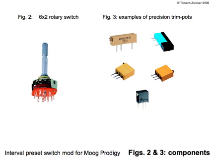
To do this mod, you will need a 6-position double pole rotary switch ("2x6", see an example Fig. 2), 10 precision trim-pots (see some examples in Fig. 3) of the sort having about 20 turns to cover their range and with a value of 100 kOhm, and some generic isolated wire. Of course, you need a soldering iron and solder, and something to drill a hole into your precious Prodigy ........
4. Knowledge requirements and preparations
Installing this mod is fairly easy for anybody having some basic knowledge about analog electronics and a bit of basic experience in mechanical workmanship and soldering of circuits.
Before doing the mod, you should familiarize yourself a bit with the circuitry of the Prodigy by downloading the schematics and service manuals from the internet. They are offered by various sites, I found them - for example - at the following addresses:
http://www.hylander.us/images/schematics/moog/MoogProdigyServiceManual.pdf
http://www.physicsenterprises.andrews.edu/diy_archive/manuals/moog/index.html#prod
http://www.pmerecords.com/Docs/ProdigyPCBLayoutsAll.jpg
http://www.pmerecords.com/Docs/Prodigy_SchematicBelow4160.jpg
http://www.pmerecords.com/Docs/Prodigy_SchematicAbove4160.jpg
http://www.pmerecords.com/Docs/ProdigyAlignmentBelow4160A.jpg
http://www.pmerecords.com/Docs/ProdigyAlignmentAbove4160.jpg
I recommend having an thorough snooping around in the insides of your Prodigy before starting modifying it. Use the circuit diagram and circuitry description together with the picture of the printed-circuit-board layout to locate the position of important circuit parts - for the present mod this will be in particular the "INTERVAL"-control.
5. Installation
Installation is done according to the schematics shown in Fig. 1. The schematics can be seen as two parts (which in fact also differ cosmetically in the figure): one part on the right is a copy&paste-job from the original Prodigy schematics and shows the interval control with the associated components R19 and R21. The other part left of it is the actual modification.
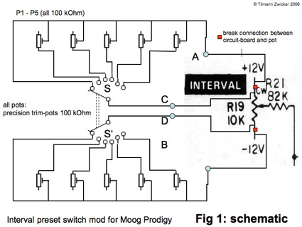
First, the interval control needs to be isolated from the -12V and -12V supply voltage fed to its outer terminals. This is represented in Fig. 1 as red blocks in the outer connectors of the interval control.
Since the corresponding conductors on the circuit board do not exclusively serve the interval control but lead on to other circuit parts, they should not be cut (although this could be done but then one would have to construct a "bypass" on the board). Rather, the left and right interval control connectors should be carefully unsoldered and pulled out of the circuit board (this may involved disassembling the pot from the board and the control panel) so that they are isolated and individually accessible.
The 6 position rotary switch should now be mounted. Since I used it as an important performance control, I drilled a hole in the lower angled portion of the control panel right above the wheels. This position is most appropriate for the present mod since it involves adjustments to pots soldered to the switch which therefore need to be accessible in a reasonably easy fashion.
Make sure you understand which contacts the switch connects in the respective position to get all connections correctly done as shown in the diagram! Because this is rotary business, it can get a bit confusing .... in reality, things will be the mirror image on one side of the switch compared to the diagram!
The two solder points on the Prodigy circuit board which were originally occupied by the now isolated connectors of the interval control are now connected, respectively, to the two centre-poles of the rotary switch.
You now need the 100 kOhm precision trim-pots. Their taps (middle connectors) are soldered to 10 of the 12 taps of the rotary switch such that they are always connected in pairs to the centre-poles of the switch. One tap on each side of the switch is not connected to anything so far. The pots should be soldered to the switch such that they can be easily adjusted.
One of the connectors of the pots remains unattached. This will be the respective connection on the "far side of the switch" ( ;-))) ) i.e. the connection located closer to where the fastening thread of the switch is.
All respective other connectors of the pots on one side of the switch (those belonging to the same of the two centre taps) are connected together. This is done best via two pieces of wire bent so as to accommodated the connectors of the pots for soldering. The wires should be cut to be longer than necessary to connect to the pots because they need to be soldered, individually on each side of the switch, to the remaining taps on the switch (those not connected so far).
Concluding the installation, two wires are soldered to the disconnected terminals of the interval control, and the other end of the wires are soldered, respectively, to the wires connecting all pots and the 6th-tap of the switch.
What we have now is an arrangement where, when the switch is in the position where the 6th tap is connecting the +12V and -12V coming from the circuit board directly to the interval control, thus yielding a function exactly as the unmodded Prodigy, while all other switch positions yield intervals and detune ranges for Osc 2 adjustable via the pots.
6. Adjusting the trim-pots
The 10 pots need now to be adjusted. This will take a while because the pots both limit the range of the interval control (i.e. setting the beating of the two oscillators) and adjusts the interval in each of the switch-positions.
You now need to switch the Prodigy on and position it such that you have access to the 10 pots as well as the interval control. Take care not to electrocute yourself, i.e. stay away from the mains power inputs and associated wires and connections!!
Select the position of the rotary switch such that the 6th tap (the one without a pot) is engaged. The interval control should function as before.
I would recommend starting with the pair of pots next to the respective 6th tap of the switch. Select the corresponding position of the switch. Depending on the setting of the pots, the interval will more or less jump somewhere, and the range of the interval control will be different. Now adjust the pots such that their effective resistance value (the pots act only as variable resistors, not as voltage dividers) is rather high. Set the interval control to unison and listen to the beating of the oscillators. there will be probably lots of it! Now adjust one of the two pots associated with the engaged switch position until the beating becomes as slow as at all possible. Check the range of the interval control. It should give you a nice control over the beating but not very extreme values at all - maybe 1 or 2 semitones. If the range is not big enough, adjust both pots to a smaller value, if the range is still to big, adjust to a higher value until the range is acceptable. Always make sure that in the unison position of the interval pot, the beating is very slow. There will be some temperature drift so that depending on the environment, the beating will change somewhat with time, but the adjustment of the way the oscillators beat against each other is much more precise and fun to do compared to before.
The other pairs of pots are adjusted in exactly the same way - however, instead of targeting unison for the mid-position of the interval control, you adjust for the interval you desire to have when that position of the switch is engaged.
That should set you up! Enjoy playing leads in which you suddenly jump to intervals without fiddling with the interval control! Enjoy working with much better controllable beating of the oscillators against each other.
7. Mod the Mod
Of course, this modification can be modified! For example, if you need only one or two intervals to jump to, a simple single- or double-throw two-pole switch will do the job. You just use correspondingly fewer pots .......
8. Note:
Although I have installed this mod successfully in my Prodigy back in 1981 and have used it for a number of years (until I sold the synth) to very good effect, and although I cannot see any risks of the mod to the synth, I also cannot take any liability with respect to any problems or damage you might incur when doing the mod. You do this entirely at your own risk.
This description and installation instruction is written in good faith with the sole intent to proved a service to the interested public. There is no commercial intent whatsoever. Hope you like it!
9. Credits:
Thanks to my friend Matthias Schorer for enduring support and the use of his website to post this mod!
Thanks to Bob Moog for creating lots of great hardware and promoting it so well!
Download this text as PDF
Download Schematics as PDF